Zusammenfassung
The development of a custom printed circuit board (PCB) for a trail camera focuses on maximum energy efficiency through the direct use of the ESP32-S3 module and a modular plug-in system for sensors. By providing hardware support for two different camera models as well as integrated charging functions, a robust base station is created that offers both flexibility and reliability.
Diese Zusammenfassung wurde mit KI-Unterstützung erstellt.
In Part 1, I described why I am building my own trail camera and why I abandoned the path of using perfboard and a soldering iron. This part tells how the concept became a real printed circuit board (PCB) and what happened during the commissioning process. Let me tell you upfront: time and patience are crucial.
The most important design decisions
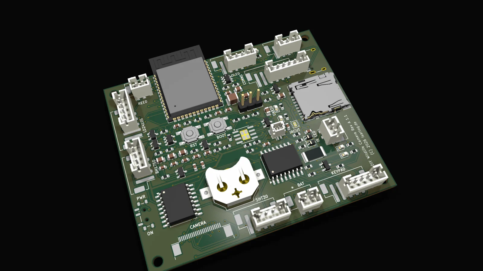
The module directly on the board. Instead of a finished development board, the ESP32-S3 module sits directly on my PCB. This eliminates all consumers that come with a dev board, from the USB chip to the power LED. Every microampere counts when six weeks of battery life is the goal.
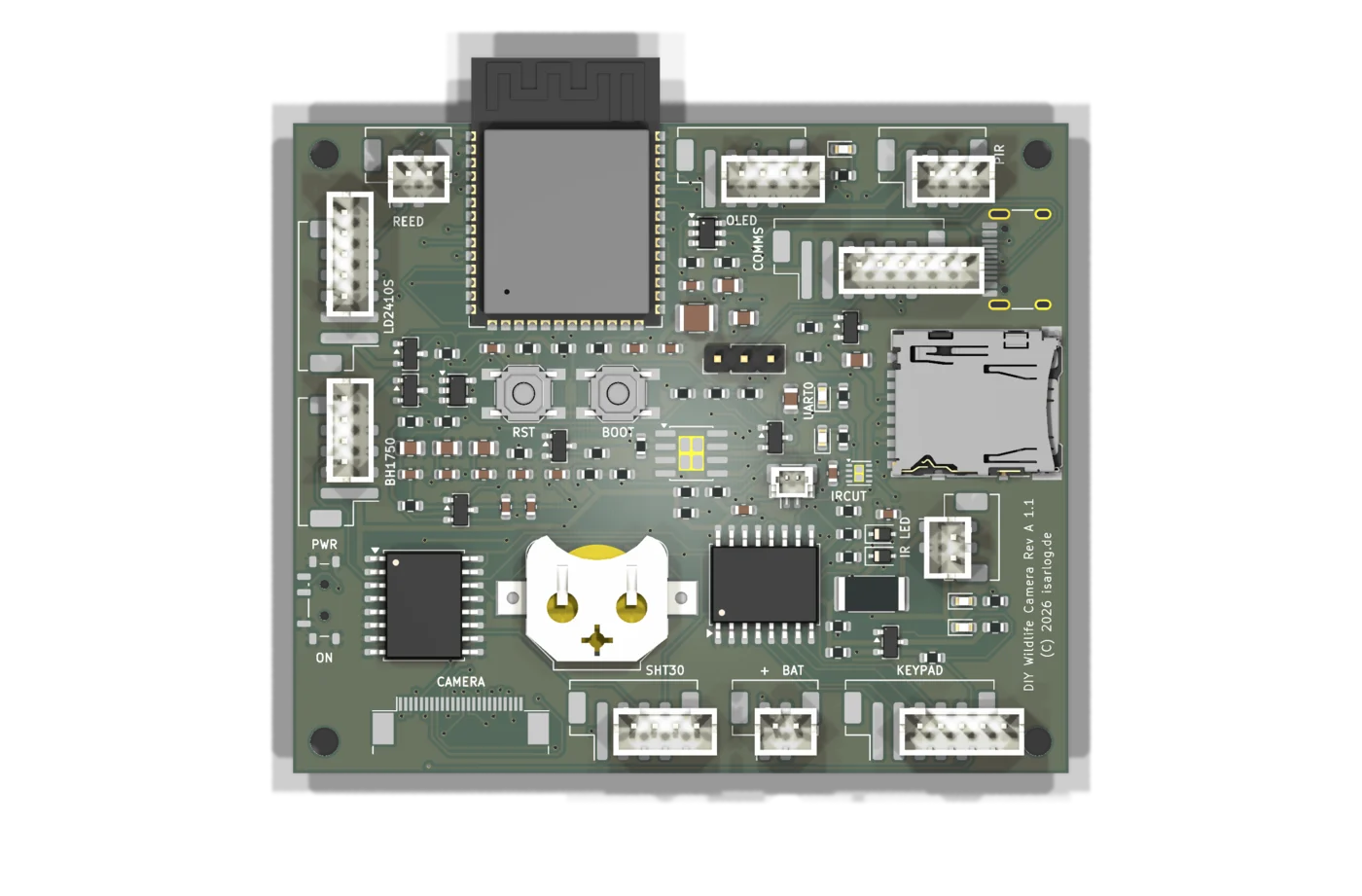
Everything pluggable. The camera, radar, PIR, light and climate sensor, display, and the later cellular module are connected via headers. This makes the PCB a base station where I can swap modules. Also, the buttons sit on a port expander, which saves valuable pins on the main chip.
Two cameras, one board. The circuit optionally powers an OV2640 or the OV5640 with its different core voltage. The firmware tries both variants at startup and remembers the result. The OV5640 is the higher-quality model with its 5 megapixels.
Fail-safe where mechanics are involved. The mechanical IR cut filter of the OV5640 is switched via a small motor driver. Its power supply is deliberately connected to the switchable camera domain: if the firmware crashes or the chip restarts, the coil is hardware-disconnected from power.
Charging without detours. A CN3058E charges the LiFePO4 cell directly from the USB-C port. Two LEDs indicate charging and full charge. The battery itself has its own BMS.
Manufacturing: Small series instead of single pieces
The board was designed in KiCad and manufactured and machine-assembled as a small series of two pieces. The total component cost was around 92.50 euros including taxes, excluding parts like PIR, temperature sensors & Co. For a hobby project, you have to be willing to spend that.
The actual work before ordering is clearly the verification. I had to check every component number against dozens of datasheets, every header against its opposite side, and every polarity against the schematic. However, the service provider from Asia was a great help and could assist quickly with problems. For a product in this price range, I know from my own experience that probably not even anyone would pick up the phone in Germany.
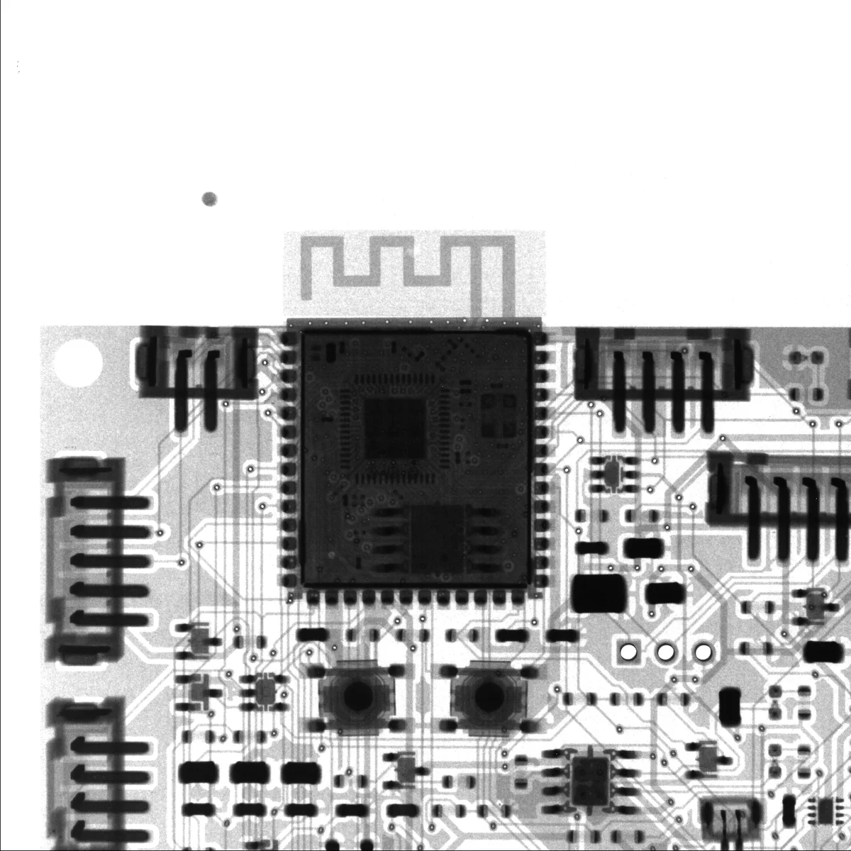
At the end, the manufacturer also sent X-ray images of the assembled boards. They show what cannot be seen in any photo: the solder joints under the wireless module, the vias between layers, and even the chips inside the module. For me, this was the most reassuring confirmation of the entire order. When I later sat for days on a seemingly unsolvable malfunction, I could at least rule out soldering quality from the list of suspects.
Commissioning: A lesson in humility
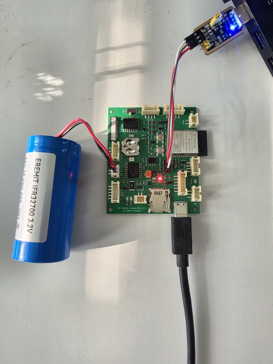
The boards arrived, looked flawless, and then the real adventure began: the firmware could not be uploaded. The chip restarted every second, the programming mode seemed unreachable, and in the meantime, I doubted everything from the boot button to the actually perfect solder joints. However, I knew from other projects that the ESP32 can sometimes be picky.
In the end, it was a chain of three causes:
- Supposedly defective Boot or RST buttons turned out to be functional after several measurements with the multimeter. I had already started tinkering with jumpers on the breadboard again.
- Without a battery, the power supply collapses. When activating the programming mode, the chip draws slightly more current briefly; the board collapses, the chip restarts, and the game begins anew. With a connected battery as a buffer: rock solid. This realization is now at the very top of the to-do list for Revision B. I somehow hadn't kept that on my radar.
- A single wrong byte in the assembled firmware package. The tool had changed the flash mode in the bootloader header during assembly. The chip subsequently entered a crash loop until the individual files were flashed separately.
The Cockpit: Maintenance without cables
After the first successful start, I gave the firmware a web cockpit as the first priority. For this, the camera opens a WLAN session upon request, and in the browser, I can see everything the device knows: the battery voltage as a trend curve over two hours, the status of every assembly, a live log of the firmware, and the files on the SD card. I can trigger a test photo, click the IR filter, set the clock with a click, and upload new firmware directly in the browser. The device writes it to a second memory area and boots into it. If something goes wrong during this process, the old version simply continues running.
To ensure the runtime goal is not compromised, a strict session model applies: WLAN is always switched on by me via button, menu, or with a magnet on the housing. It is always switched off by the device itself after fifteen minutes of inactivity. In field operation, it remains completely off.
The reward for all this: The programming adapter now sits in the drawer. Updates, diagnostics, viewing photos—everything runs wirelessly. And the battery monitoring has passed its baptism of fire: observed charging curve, verified full charge, measured voltage behavior under load—all from the desk.
What will be different in Revision B
Developing your own hardware means keeping an honest list of errors. The most important points for the next board revision:
- Enable operation without a battery. The power supply needs enough buffer to withstand load peaks even during pure USB operation.
- The boot pull-up moves to the correct rail, so that a voltage drop can no longer force the chip into programming mode.
- The charging status becomes measurable. Currently, only two LEDs know it; in the future, free chip inputs should read it so that the cockpit can directly display "charging" and "full."
Outlook
The board is already capable of basic functions, but with the attachment of the remaining parts, it will have to prove whether my plan works and if a functioning DIY trail camera stands at the end. In Part 3, we will look at its home: a 3D-printed housing produced via self-printing.