Zusammenfassung
The development of a compact DIY wildlife camera relies on the targeted selection of low-cost and unobtrusive components, such as the ESP32 microcontroller. By using specialized sensors and batteries, a high-performance, pocket-sized device for nature observation is realized.
Diese Zusammenfassung wurde mit KI-Unterstützung erstellt.
Table of Contents
- Planning Phase - Compact and Unobtrusive
- Choosing the Platform: ESP32 instead of Raspberry Pi
- Power Source: Why LiFePO₄?
- mmWave instead of PIR Sensor
- Temperature and Humidity
- Night Vision: 850 nm instead of 940 nm
- Where are the photos stored?
- Logic, Error Messages, and Status
- External Light Sensor
- Outlook
- The Price
- The Parts List
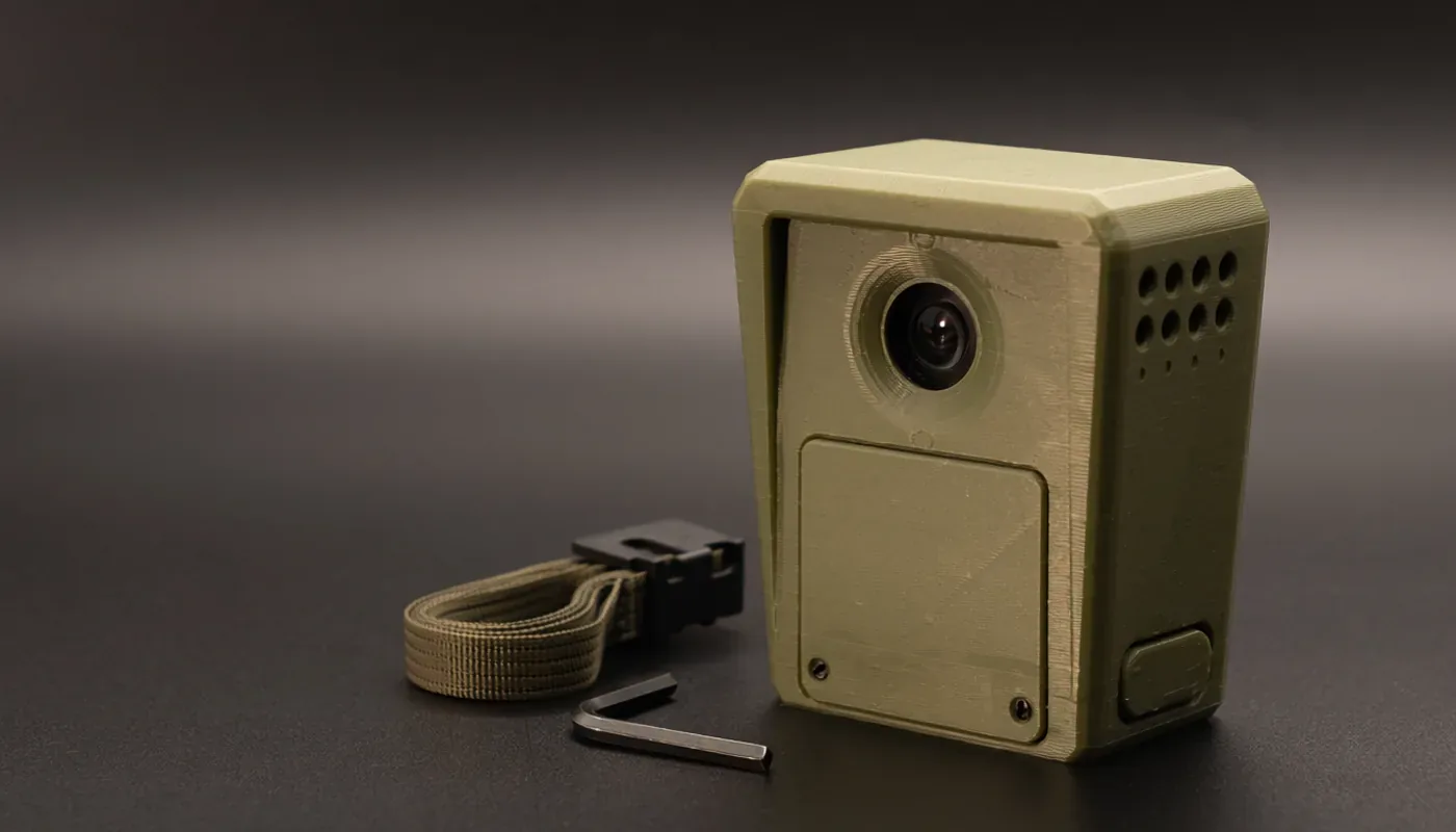
"The goal is a DIY wildlife camera in pocket size"
– Sebastian Meisinger, Isarlog
Planning Phase - Compact and Unobtrusive
Wildlife cameras are a fascinating tool for nature observation. However, every time I looked at the models available on the market, I noticed the same thing: they are large, conspicuous, expensive, and offer little room for customization. Additionally, in our densely populated areas, theft is always a risk even in the forest—and if a camera costing 100 euros or more disappears, it is a major nuisance.
That is why I decided to build my own wildlife camera. The goal is a device that is barely larger than a deck of playing cards or a power bank. The component prices should be chosen so that a loss remains bearable. Furthermore, I want to have control over every single component. Using a 3D printer, I can freely determine the housing shape and color, ensuring the camera blends much more harmoniously into its surroundings and does not immediately stand out.
Choosing the Platform: ESP32 instead of Raspberry Pi (Pico, Zero)
First, the question arose: which controller should be the heart of the camera? A Raspberry Pi Zero would have been the obvious choice—after all, the image quality with Pi cameras is very good. But upon closer inspection, it became clear: the Zero is practically useless for a battery-operated wildlife camera. Even in idle mode, it consumes too much energy, and there is no true deep-sleep mode. A runtime of weeks would therefore be impossible.
The Raspberry Pi Pico initially seemed more attractive. It is more power-efficient, can be combined with camera modules, and has a broad developer base. But even here, one quickly hits limits: the camera modules are less powerful, software support is more restricted, and there is a lack of established infrastructure for simple, low-power image capture.
This left the ESP32-CAM—specifically the variant with the ESP32-S3. It offers a direct camera interface, deep sleep with a consumption of only a few microamps, integrated WiFi (for potential future expansions), and sufficient computing power for image capture. In short: it combines everything I need for an ultra-compact and efficient wildlife camera.
Power Source: Why LiFePO₄?
The choice of battery was no less decisive. Lithium-ion or polymer batteries are widely used, but both have disadvantages: they are more sensitive to temperature fluctuations, age faster, and pose a higher safety risk. In the forest, during frost or summer heat, I do not want a cell that could, in the worst case, overheat or even become a fire hazard.
LiFePO₄ (Lithium Iron Phosphate) offers the best solution for me. The chemistry is safer, the cells remain stable even at adverse temperatures, and the nominal voltage is 3.2 volts—ideal because the ESP32 operates at 3.3 V. This eliminates the need for a lossy voltage converter. With a chosen capacity of 6000 mAh, I can achieve a runtime of four to six weeks under typical use.
mmWave instead of PIR Sensor
A classic PIR sensor would have been the simple solution. However, PIR sensors have known weaknesses: they are prone to false triggers caused by wind, light reflections, or passing insects. For a wildlife camera hanging unattended in the forest, false triggers are fatal—the battery would quickly run out and the memory card would be full of empty images.
Therefore, I chose an mmWave sensor (LD2410S). This detects motion more precisely, even through thin materials, and distinguishes better between real objects and random disturbances. This makes the camera more reliable and saves significantly more energy during operation.
Temperature and Humidity
Additionally, an SHT30 sensor (encapsulated, I²C) will be integrated to measure the ambient temperature and humidity. This allows me to capture environmental conditions that make every recording more interesting.
Night Vision: 850 nm instead of 940 nm
Another important decision concerned the infrared illumination. Ready-made wildlife cameras mostly work with 850nm, while some use 940 nm LEDs, which are completely invisible—but the price for this is that the range is significantly lower and the image quality suffers. In contrast, 850 nm LEDs provide a brighter image and better range, but they are visible as a slight glow from close range.
Since I want my camera to be as inconspicuous and small as possible, the residual risk is acceptable. At a distance of two or three meters, the glow is hardly perceptible, and experience shows that animals do not react to it. Finding a suitable lens was more difficult: small modules with a good field of view and simultaneous night-vision capability are not easy to come by. I had to compare for a long time before finding a suitable combination.
Where are the photos stored?
An ESP32 does not have a built-in storage function for images. To make this possible, I will integrate a common MicroSD card module (SPI). The photos will then be stored there.
Logic, Error Messages, and Status
For the camera to work reliably in the field, it needs more than just a trigger. A self-test upon startup should check all components—camera, sensors, storage—and report the status. I have planned two levels of feedback:
- A bi-color LED directly shows the state ("Ready" or error)
- An OLED display (SSD1306, 0.96″) provides more detailed information: whether the SD card was recognized, whether the sensors are responding correctly, or if there is an error in the process.
This provides both simple visual feedback in the field and a detailed diagnosis in case something does not work as planned. This allows the camera to independently indicate whether it is ready for use or if action is required.
External Light Sensor
To ensure the camera can reliably distinguish between day and night, an external light sensor will also be installed. A simple photoresistor on the main board would be too imprecise and susceptible to moisture, so I chose an encapsulated sensor that is mounted outside the housing. It reliably detects ambient brightness and automatically switches on the IR LEDs when darkness sets in. By moving it outside, the sensor is protected from the weather and provides more stable values.
Outlook
This is the first prototype. My goal is not to build the perfect camera immediately, but to create a foundation that I can build upon. In the future, variants can be easily developed: with stronger IR illumination, a better camera, or additional sensors (temperature, humidity). The great advantage of the DIY approach is exactly that: I have full control over my system, can adapt and improve every component—and all at a fraction of the cost of a finished camera.
The Price
With this, I have planned a wildlife camera for approximately 35 euros that will be more compact, flexible, and inconspicuous than much of what is available on the market. And the best part: should it ever go missing, the loss is bearable. Although, of course, it would still be a shame. For me, this is the perfect entry into a series of my own, further developed DIY wildlife cameras.
The Parts List
Control
- ESP32-S3 board with camera interface
Camera
- 2 MP: OV2640 camera module (NoIR version, without IR filter) or
- 5 MP: OV5640 camera module (NoIR version, without IR filter) – alternative with higher resolution
Motion Detection
- LD2410S mmWave sensor
Light Sensor
- BH1750 encapsulated I²C module
Climate
- SHT30/SHT31 temperature and humidity sensor (encapsulated version, I²C)
Night Vision
- IR-LED 850 nm, 1 W on Star-PCB (3 W would be too power-hungry)
- Resistor 4.7 Ω, 1 W, metal film
- MOSFET AO3400 (N-channel, logic-level)
- Heatsink for the IR-LED
Storage
- MicroSD card module (SPI, 3.3 V compatible)
- MicroSD card (8–32 GB)
Power Supply
- LiFePO₄ battery with BMS (6000 mAh)
- TP5000 charging board (1S LiFePO₄, JST)
- Fuse
Display / Feedback
- 0.96″ OLED display (SSD1306, I²C, 128×64)
- Bi-color LED (red/green, 3 mm, cathode)
- Resistors: 220 Ω
Construction / Mechanics
- Perfboard (protoboard, 2.54 mm, FR4, 1.6 mm)
- Cables, connectors (JST)
- PETG housing (cigarette pack size, 3D printed)